table fan :-
Introduction to Table Fan
A propeller blade fan comprising two or more blades is directly driven through an electric motor. It might be a bracket mounted wall kitchen fan, table fan, or a portable table fan. Four blades table fans are as well available to acquire more air delivery.
Parts of Table fan:
The main parts of the ceiling fan are displayed in the below diagram. The major components are the following;
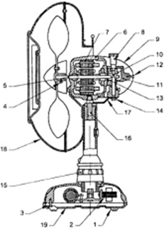

Diagram - Internal parts of table fan
| 1. Rubber Feet | 11. Gear Box |
| 2. Regulator Choke | 12. Back Cover Fixing Screw |
| 3. Capacitor | 13. Bush Bearing |
| 4. Blade Bush Fixing Screw | 14. Link Fixing Screw |
| 5. Spindle | 15. Switch |
| 6. Front Cover | 16. Pivot Pin |
| 7. Stator | 17. Crank Lever |
| 8. Oscillator Knob | 18. Wire Guard |
| 9. Back Cover | 19. Bottom Cover |
| 10. Vertical Spindle |
Enclosure:
The place in which the fan motor is mounted might be totally enclosed type or ventilated type. The enclosure material is usually cast iron.
Body and stand:
The body of the table fan is generally made up of die cast iron or aluminum alloy. The body is fitted or mounted to the heavy base stand, made up of die cast iron or aluminum.
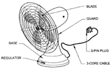
Diagram - External parts of table fan
Motor:
The table fan motor is mainly of a single phase capacitor start and run or seldom shaded pole type motor. The motor's operating voltage will be 230 V ± 10 % at a frequency of 50 Hz. This motor contains two parts that are stator and rotor. The stator, made up of laminated silicon steel, uses two windings termed as starting and running windings located 90 degree electrical apart. The windings are located in slots of laminated iron core. The starting torque relies on sine of angle among starting winding and running winding current. Thus Capacitor is employed generate needed phase shift between these current and therefore to generate high starting torque and will be connected in series with starting winding. Generally in table fan, an electrolytic capacitor of 1.5 mF. Rotor uses 1-phase squirrel cage winding.
Blades:
The blades, 3 or 4 in number, are made-up from Aluminum sheet foe light weight. Recent table fans comprise molded blades of plastic material. The blades are completely balanced to make sure proper and smooth air delivery. The sweep of the blade changes from 100 to 400 rpm (Revolutions per minute). The fan's speed is limited to less than 1000 rpm (Revolutions per minute). The blade assembly is built-in to the rotor shaft along with a grub screw.
Guard:
The guard is given for sufficient protection against personal injury. The front and rear of the fan guards are made out of wire mesh which covers the blade. It prevents the external objects coming in contact with the blade so avoiding an accident. The front guard is generally detachable and rear one will be lastingly fixed to the body of the fan. The diameter of the guard wire is generally not less than 1.6 mm and not additional than 10 mm.
Bearing:
Several fan motors make use of phosphor bronze sleeve bearings mounted in the bell housings and make use of felt wick to supply oil to a small hole drilled by the bearing wall. In the bell housing the felt wick receives oil from a hole. Several fan motors employ an integral ball bearing to place the rotor. It is held in place through spring clips in the bell housing and is self-aligned.
Mounting:
Mounting means attaching the fan system (motor and blades) to its bottom. The mounting might be rigid (change of direction is through turning the complete fan body) or semi-rigid (the direction of draught can be changed without changing the direction of the base).
Oscillating mechanism:
The oscillating mechanism contains a worm gear or a motor shaft which engages a gear on a short jack along with the gear on the vertical shaft. A disc that attached to the lower end of the vertical shaft rotates at a extremely slow speed and by way of a strong crank lever attached to the disk at one end and the motor at the another end, the fan is caused to oscillate. This standard is used in several oscillating units built into the gear mechanism along with a compression stud device. This design allows the fan to be employed either as a stationary or an oscillating model.
Supply cord:
A 3 core, flexible sheathed conductor of length about 2 m is employed that has an earthing conductor together with other two conductors. A cord grip is as well inserted at the entry point of cord into the body.
Fan regulator:
Fan regulator is built in the table fan. There are several types of regulators
i) Resistance wire type
ii) Choke or inductor type
iii) Capacitor type and
iv) Electronic type.
Usually coiled resistance type regulator is employed in table fan.
12 Volt to 220 Volt Inverter 500W

It easy to make and Low cost.
Friends favorite circuit about the the inverter, because like working outdoors, or to backup storage to use when necessary.
Most of this is circuit low power, which is not suitable for practical applications. My friends said that he would be about 500 Watt.
Most of this is circuit low power, which is not suitable for practical applications. My friends said that he would be about 500 Watt.
It is a good size. Use with television receivers and light bulbs as well.
When looking for circuit. I get headaches. If you are a beginner or I can not buy expensive good quality circuits. Requires only one transistor. Or if you have free time. I want to build old circuit is alive again. This circuit will accommodate all your needs. It is a simple circuit. The same principle, I take battery voltage 12V to produce a oscillator about 100 Hz and pass to a two frequency divider circuit is only 50HZ. And drive a 10 ampere transformer with 10 x 2N3055 transistor in parallel. By a single transistor has 2A, when I use 10 transistors or 5 pairs of drive high current output. The complexity of circuit, but the principle is not it, and it is the number of transistors on a basic, easy to buy.
FM wireless transmitter circuit
This the fm wireless transmitter circuit, the truth is one kind microphone that developed to be used without a cable from the microphone to the amplifier. Makes flexible to use than a plain microphone much Because without cumbersome cables. And also save a microphone cable as much Because microphone cable is high quality that has relatively high prices.
How it work
When we speak, the microphone will receive the audio signal is mixed with range FM frequency to transmit the broadcast spectrum. The audio input is just bring to the FM radio receiver tuned provide the radio only. The detailed procedures are as follows.
In Figure this circuit has very little equipment, MIC is used in the circuit be special that called the condenser microphone, inside the MIC has an one amplifier section Serves to amplify the voice that speaks to the strength increases and send to the output. So this MIC must a current one to them. Please note the circuit is supplied to the resistor 27K positive in the leg microphone,and it is way out of with the audio signal,through the coupling capacitor to pin B of Q1,

Which Q1 also acts as both the radio frequency generator and the audio mixer on the Radio frequency is generated. and at B pin of the Q1 have the resistor R2 – 27K with R3 – 4.7K are divider circuit, Divided a number of voltage to the bias for Q1. and the capacitor C2-0.01uF is connected to ground for bypass the high frequency, At C pin of the Q1 is connected pass the coil to the positive voltage
For this coil, we use copper wire No. 19-20 AWG, wrapped around the air core diameter of 7 mm. You should be bind seven around , similar to coil spring, Then, stretching out to Length of 15 mm. close this coil has a capacitor C4 value 5-20pF is the capacitor to adjust from 5pf to 20pF we called that the timmer. It is connected to a frequency tuning
And pin C of Q1 is connected to the antenna. Which in this circuit, we use an antenna that is built with yourself. By using number of wire 16-20 AWG, about 7 inches in length, and curled into a circle like a spring, about 6 mm in diameter, the length of the wire coil to the the end, then take one end soldered to the antenna connection.
Creating and use
You should be include before small device. The condenser MIC should be use the shielded cables in length about 5 cm to connect from the PCB. We use the coated copper wire for to prevent rust green from moisture in the air. At the end of the wire must be soldered, the need for razor blade to scrape out a solution. so is soldered on. The use of lead solder, lead to a better mix of 60/40, and requires some skill in soldering. Otherwise, the spectrum could not be removed. It is a high frequency.
You should be include before small device. The condenser MIC should be use the shielded cables in length about 5 cm to connect from the PCB. We use the coated copper wire for to prevent rust green from moisture in the air. At the end of the wire must be soldered, the need for razor blade to scrape out a solution. so is soldered on. The use of lead solder, lead to a better mix of 60/40, and requires some skill in soldering. Otherwise, the spectrum could not be removed. It is a high frequency.
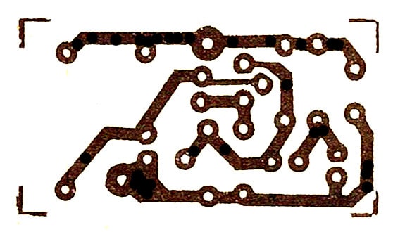
Figure 2 The PCB layout and Components layout of FM wireless transmitter circuit
When completed, the FM radio is one, open to the FM radio dial in the middle. When turn on the FM wireless transmitter circuit then use a screwdriver plastic or plastic sheet flat spin adjust the trimmer And speak into the microphone, to tune until has the sound to the FM radio. if tune the trimmer until full cycles, Not yet match wave, try stretching or shrinking of the coil, then adjust the new one, maybe try some stretching or shrinking the antenna, in order to deliver the best results. If all the fine tuning do still does not work. Also, try turning the radio waves, may be rotated to the minimum frequency, maximum frequency, or turn around the station. Then try adjust it again. When adjust until available, they may be find a plastic boxes or aluminum boxes or a box ready to build up own. By folding a sheet of aluminum or a plastic sheet is glued to the box for convenience to you.
Note: Principle, this circuit send far about 100 meters, Depending on the location. There is low or high of noise oscillator, Equipment with high quality or not, The soldering is good or not, Therefore, it is difficult to determine how far? But from my experience, in the center of the floor to the fourth floor of the building, it has been, they think that’s enough for the circuit with very little equipment, and low cost of this.
How to make a portable handy lie detector in Altoid tin

This is a portable lie-detector built in Altiod tin. maybe you could have some fun useing this thing.
note: this detector is less sensitive then a real one. this could be miss some (many) of the lies.
Step 1: Things you'll need.

You will need some things below for this project.
1. circuit board
2. 10K& resister
3. 47K& resister
4. 470& resister
5. 1M& resister x2
6. 47K& VR
7. knob for VR
8. 2N3904 transistor x3
9. 0.1 ? mylar cap
10. slide switch.
11. 9V bettery snap
12. LED (one red, one green)
13. solding tools.
14. drill
15. basic tools,
16. valcro
17. aluminum foil
....and most of all, Altoid tin!
Step 2: Make a finger pads

make a finger pads by sticking a aluminum foil to the valcro.
And don' forget to stick a wire between the valcro and thw foil!
And don' forget to stick a wire between the valcro and thw foil!
Step 3: Solding the circuit


Solder the circuit as a diagram below. And before solding the circuit, cut the circuit board to
suitable size to fit in the Altoid tin
suitable size to fit in the Altoid tin
Step 4: Drilling the Altoid tin

Drill the Altoid tin for a VR.
and DO NOT use a sharp-end drill bit. it will tear the tin into half.
and DO NOT use a sharp-end drill bit. it will tear the tin into half.
Step 5: Put the floor sheet

Put the floor sheet in a floor of the tin to avoid circuit from 'shorting'.
and secure is with a glue.
in my case, I used a piece of box, and secure with a hotmelt.
and secure is with a glue.
in my case, I used a piece of box, and secure with a hotmelt.


Old-World Light Bulb Load
Step 1: Electrical Parts

I started by finding the essential electrical parts. I found the small porcelain light bulb sockets at Home Depot, and I picked up the standard 5-way binding posts from Radio Shack. I have to admit that I was very tempted to use knurled brass thumb nuts instead of modern binding posts, but since this device is also meant to be useful, it has to accept banana jacks, and so I resigned myself to having a little bit of plastic.
My original plan was to simply mount all these parts to a board and get back to work on my power supply. The problem was that the binding posts expect rear connections. The light sockets are more flexible, but they do allow rear wiring.
I quickly came to the conclusion that I would need a box.
My original plan was to simply mount all these parts to a board and get back to work on my power supply. The problem was that the binding posts expect rear connections. The light sockets are more flexible, but they do allow rear wiring.
I quickly came to the conclusion that I would need a box.
Step 2: The Box


With the idea in mind that I would need a box to mount these parts on, I started looking around my workshop for something suitable. I had plenty of plastic and metal project enclosures, but nothing had the right look. Finally my eyes came to rest on a sheet of oak craft board that I had sitting next to my scroll saw.
The board was 5.5" wide, just big enough to mount the two fixtures side by side. I measured off a piece 4" long and cut it. Then I measured a set of pieces a nudge more than 1" long, and cut those off. Two of them I left 5.5" long, two of them I cut down to 4" long.
I measured and marked the location of fingers for box joints, marking on the inside surfaces the order in which they assemble. This is important: while they are all measured the same way, they only go together in one order, as slight errors occur from freehand cutting.
I cut the slots out with my scroll saw. To make these square cuts, start by cutting two slots straight in, keeping the blade on the waste side of the line. After cutting to the final depth, back the blade straight out. Once both slots have been made, put the piece back into the blade at an angle, cutting through the waste piece while turning, reaching the bottom about half-way between the two slots. At this point, the blade should be facing in the right direction to finish half the cut, resulting in a nice sharp corner. Then just make another cut, starting from where the last cut began, but in the opposite direction, making another sharp corner.
The mating pieces will usually not fit the first time you try. I used the scroll saw to take off paper-thin curls of wood until the parts fit. You could do the same, or if you are not as comfortable with scroll saw operation, you could file them down with a wood rasp.
After the box was ready to assemble, I marked and drilled all the mounting holes.
Step 3: The Brass Plates

No old-time woodworking project is complete without a touch of brass. The shiny yellow metal complements stained hardwood nicely. This was one of the most complicated parts of the project, and not even strictly necessary, but it looks good.
I started with some craft store brass strip, which I cut to length. Brass is remarkably difficult to cut with a scroll saw. My first attempts caused a blade break, so I searched the internet for advise before continuing. It turns out that the trick is to use a backer board, so I picked a lump of pine from my scrap bin and put it under the brass. After that, the scrolling went smoothly, although slowly and noisily. I imagine that the correct tool for the job is an abrasive band saw, but I do not own such a tool.
After cutting, I rounded the corners on a stationary disk sander. I then tilted the sander table to a 45 degree angle and beveled the edge. The resulting edges were rather sharp, so I cleaned them up on the sander without using the table. When using a disk sander without a table, hold the piece at an angle away from the direction of rotation. Otherwise, the grit will catch the workpiece, and even assuming you can keep a grip on it, this will cause the piece to vibrate. Holding the piece at an angle causes the grit instead to push the piece away from the wheel, allowing fine control and reducing the amount of material it removes.
I then took the plates over to my drill press and drilled out the mounting holes. I have to admit that I made a mistake here. Brass is a slippery material. Make absolute sure that you have a good center punch before trying to drill it, and drill a pilot hole. My own center punches were not well enough defined, and the pilot holes drifted. Thankfully, I managed to mostly correct their locations before drilling the mounting holes. Mostly.
After that, one thing led to another, and I had managed to scratch the brass. Brass is, after all, a relatively soft metal. I sanded it down with 400 grit sandpaper. If I had any 200, I would have started with that, and it would have given me better results. After sanding with the 400 grit, I ran over it with a Dremel wire wheel, giving it a nice shiny brushed appearance.
Some time after I took this picture, I decided to refinish the brass parts, as I had picked up some 220 grit sandpaper. I did it the same way, but I decided to forgo the wire wheeling.
Step 4: Gluing the Box

Because friction fit is never enough, the time arrived for me to glue the box together. I used Elmer's brand "Stainable Wood Glue", because I figured that I would probably end up with glue in a few random places and a stainable glue would probably help to hide it when the time came to stain the wood.
I started by taking the workpiece to the scroll saw and enlarging a couple corners to improve the fit under pressure. If anything, I may not have been aggressive enough in doing this, but it helped a lot.
I rolled out a sheet of aluminum foil, poured a little glue out onto a corner, and used a Q-tip to apply the glue to the mating surfaces of the box joint. As the process is rather time sensitive, I wasn't able to actually get pictures of this step in progress.
After the glue was applied and the box was assembled loose, I clamped it every which way and left it to sit for a few hours.
Step 5: Surface Preparation

The next day, I removed the clamps. The box was, indeed, a single solid piece. I applied some wood filler to the surface, and scraped the excess off with a putty knife, and then left that to dry overnight.
The next day, I sanded the surface smooth with a bit of 220 grit hand sandpaper. Then, using some 80 grit sandpaper on my stationary disk sander, I cleaned up any overhangs on the box finger joints. I then rounded down all the edges and corners.
After this, I applied a second coat of wood filler and then sanded it down in preparation for surface finish.
Step 6: Surface Finishing

After filling the grain and the box joints with wood filler and sanding, I applied a coat of Minwax water-based rosewood color wood stain with a cotton cloth. I was pleasantly surprised by how well the wood filler soaked up the stain, leaving a very even finish. I then left it to dry overnight.
I waited another day for the weather to clear up, and on a nice sunny day with little wind, I applied three coats of Minwax Polycrylic matte topcoat, allowing an hour between coats, and sanding lightly with 220 grit before applying the next coat.
The results are pretty good for a first try.
I waited another day for the weather to clear up, and on a nice sunny day with little wind, I applied three coats of Minwax Polycrylic matte topcoat, allowing an hour between coats, and sanding lightly with 220 grit before applying the next coat.
The results are pretty good for a first try.
Step 7: Assembly and Wiring


The last step remaining is to assemble all the parts. I had to clear the holes with a hand-drill, as some wood filler had adhered to the insides, but otherwise, this was completely straightforward. I mounted the fixtures down with some #10 screws.
I fed some 18AWG wire through the holes in the back of the bulb fixtures, and soldered them to the binding posts. I fastened the other ends in the screw terminals. After that, I put the retaining rings on the fixtures, and added some bulbs.
I made a bottom out of a sheet of mat board from a craft store, which I cut to size using a rotary cutter. I rounded the corners of the mat board on my disk sander, which worked far better than I expected. I then glued this to the box with some rubber cement.
I was out of rubber feet, so I made some with a bit of craft store self-adhesive foam sheet. I made a punch by sharpening some 3/4" brass pipe on my disk sander, and while pressing the punch into the sheet against some scrap wood, turned it until the material was cut. This seems to be a pretty easy way of making non-marring feet, although the foam is a bit soft. I applied four of these improvised foot pads to the bottom.
Step 8: Apply Power

For the purposes of demonstration, I connected the bulbs in series and then to 120VAC.
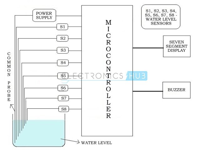
Water Level Indicator Project Block Diagram:
Water Level Indicator Circuit Diagram:
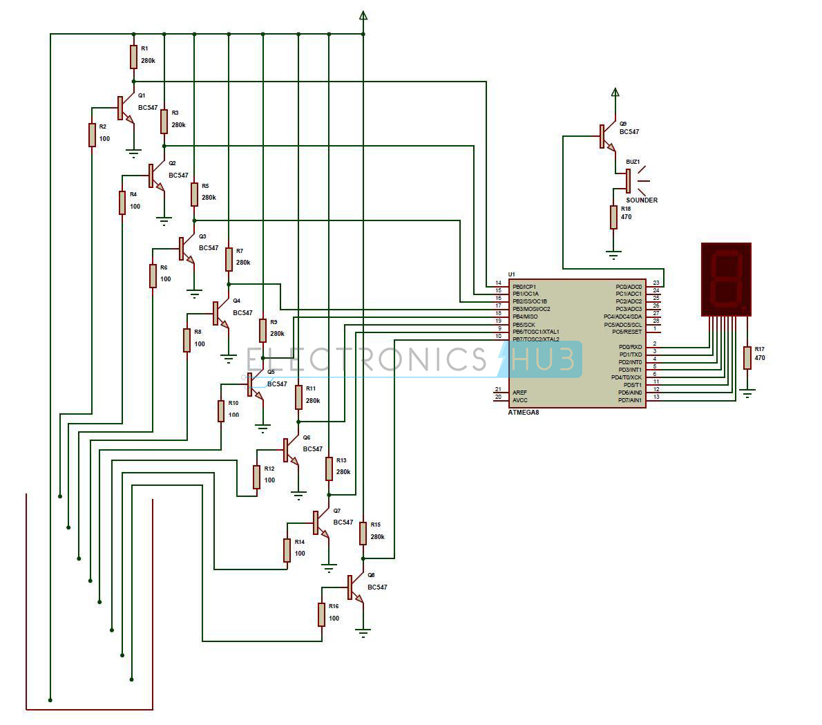
Water Level Indicator Project Description:
This is the circuit diagram and description for water level indicator.
- A constant 5v power supply is given to the microcontroller and rest of the circuit from a battery.
- The tank has 9 conductive type sensors (other types of sensors have been mentioned earlier but in our project only conductive type are used) embedded into it and 8 wires of sensors out of 9 are connected to transistors and the 9th is connected to 5v+ supply.
- The use of transistor is it acts as inverter (i.e. in on state gives low voltage at output and in non conducting state gives high voltage at its output), all transistors outputs are connected to 1,2,3,4,5,6,7,8 pins (PORTB) of microcontroller.
- Seven segment display is connected to pin no. 33 to 40 (PORTA). It is connected in common cathode fashion.
The Output for the 7th level is not only shown in seven segment display but also indicated with a discontinuous buzzer sound. - Output for the 8th level (i.e. tank full condition) is not only shown in seven segment display but also indicated with a continuous buzzer sound.
Working of Water Level Indicator Project Circuit:
The operation of this project is very simple and can be understood easily. In our project “water level indicator” there are 3 main conditions:
- There is no water available in the source tank.
- Intermediate level i.e. either of 3rd to 7th level.
- There is ample amount of water available in the source tank.
So let us discuss on the more about these 3 conditions
CONDITION 1: Water not available
When the tank is empty there is no conductive path between any of the 8 indicating probes and the common probe (which is connected to 5v+ supply) so the transistor base emitter region will not have sufficient biasing voltage hence it remains in cut off region and the output across its collector will be Vc approximately 4.2v. As in this case the microcontroller is used in the active low region (which means it considers 0-2 volts for HIGH and 3-5 volts for LOW) now the output of transistor which is 4.2v approximately will be considered as LOW by the microcontroller and hence the default value given by microcontroller to the seven segment display is 1 which indicates as the tank is empty.
CONDITION 2: Intermediate levels
Now as the water starts filling in the tank a conductive path is established between the sensing probes and the common probe and the corresponding transistors get sufficient biasing at their base, they starts conducting and now the outputs will be Vce (i.e. 1.2v-1.8v) approximately which is given to microcontroller. Here the microcontroller is programmed as a priority encoder which detects the highest priority input and displays corresponding water level in the seven segment display. In this project while the water level reaches the 7th level i.e. last but one level along with display in seven segment a discontinuous buzzer is activated which warns user that tank is going to be full soon.
CONDITION 3: Water full
When the tank becomes full, the top level probe gets the conductive path through water and the corresponding transistor gets into conduction whose output given to microcontroller with this input microcontroller not only displays the level in seven segment display but also activates the continuous buzzer by which user can understand that tank is full and can switch off the motor and save water.
Light Following Robot

Introduction:
The light following robot is a mobile machinewhich is capable of detecting and following the light source on the traveling path. It is developed without the help of a micro-controller for providing easier connections and understanding of the circuit. It requires fewer numbers of electronic components andvery cost-effective as well.
The concept of this light following robot is very simple. It includes two photodiodes, one on the right and other on the left. When the light falls on the right photodiode, the robot will move on the right side. Similarly, the robot will move on the left side when the light falls on the left photodiode.
Components used:
- Battery: One 9V battery will be sufficient for powering the robot. For more usages, two pairs of 9V battery may be required.
- Battery holder: It is used to connect the battery with the circuit.
- Breadboard: One breadboard is used for designing the circuit. The electronic components are connected by inserting it in the holes of the breadboard.
- Capacitor: Two 10uf capacitors are implemented to store the current, equalize the power output, filter, and so on.
- Castor Wheel: One castor wheel is mounted in front of the hard board for providing easy and comfortable moving of the robot.
- Gear Motor: Two 300rpm gear motors are connected with the wheel for moving the robot.
- IC 7805: One IC 7805 voltage regulator is incorporated for allowing 5V of power supply to the circuit instead of 9V.
- IC L293D: One L293D IC motor driver is used for driving two motors in both clockwise and anticlockwise directions.
- IC LM358: One LM358 IC voltage comparator is attached to the circuit for comparing voltages across the + and – terminals.
- LED: A 1.5V 200mA LED is attached to notify the falling of light source on the photodiode.
- Resistor: One 1K & three 10K resistors are required for this process to reduce the voltage. The ranges of the resistors can be calculated with the help of a multimeter.
- Wheels: Two wheels (10cm dia.) are coupled with the gear motor. When the motor is powered, the wheels will start to rotate and move the robot.
- Wires: Two meters of both two core and four core wires will be required. For breadboard connections, two core wires should be used and for motor connections, four core wires should be used.
Circuit Diagram:

Construction and Working Principle:
Connect a 9V battery to the breadboard with the help of a battery holder. The positive power supply is passed to the IN of IC 7805 (1), and sent out through the OUT (3). The negative power supply is sent to the GND (2) connection of IC 7805. In between, two capacitors (C1 & C2) are connected to the IN and OUT of IC 7805 respectively. As a result of this process, 5V of current is obtained.
Now, connect an IC LM358 in the breadboard. As it is a voltage comparator, it will predict the output from the photodiodes based on the input voltage. For instance, let us consider that the voltage at 3rd pin is more than or equal to the voltage at 2nd pin. At this time, the 1st pin of IC LM358 will be high or else it will stay low. A 10K resistor is coupled with each photodiodes. Then, place an IC L293D in the breadboard, and join the 2nd and 15th pin of it with 1st pin of IC LM358. In between this connection, include a LED with the 10K resistor.
The four – core wire of left motor is connected to the 3rd & 6th pin of IC L293D, while the right motor is attached with 11th & 14th pin. The two 10cm wheels are mounted with the motors. Acastor wheel is included at the front of the robot for balanced and comfortable movements. A power supply of 5V is applied to the 1st, 7th, 8th, 9th, & 16th pins. The remaining 4th, 5th, 10th, 12th, & 13th pins are connected to the ground.
After finishing all the circuit connections, place the robot in the dark room. Connect the 9V battery and power the robot. Now, show the light in front of the robot, and it will follow the light wherever it goes.
No comments:
Post a Comment